
A USB-A port officially delivers 5V at either 500mA (USB 2.0, up to 2.5 watts) or 900mA (USB 3.x, up to 4.5 watts). The higher currents you see advertised on wall chargers, often 1.5A to 2.4A, come from Battery Charging 1.2 signaling or proprietary handshakes, not from USB Power Delivery, which USB-A was never built to negotiate.
TL;DR:
- USB-A ports are limited to 5V and typically deliver up to 2.5 watts under standard specifications, with higher currents enabled only through proprietary signaling like BC1.2.
- The maximum current for USB 2.0 high-power ports is 500mA, while USB 3.x can supply up to 900mA, but these limits do not include Power Delivery capabilities.
- Higher advertised charging currents, such as 1.5A or 2.4A, rely on proprietary or BC1.2 signaling, not the core USB-A standard, which remains fixed at 5V.
- Claiming PD levels over USB-A ports is inaccurate since the connector lacks the necessary CC pins, and voltage negotiation only occurs via USB-C connections.
- Using proper cables, verifying port ratings, and prioritizing PD-capable ports ensures safer and more reliable high-current charging.
Table of Contents
- Standards primer: unit loads, VBUS tolerances, and where USB-A sits in PD history
- Battery Charging 1.2 and proprietary quick-charge behaviors on USB-A
- USB-A to USB-C cables: when higher wattage claims hold up
- Multi-port chargers and hubs: how shared power budgets work
- Safety, thermal limits, and when to retire a cable or port
- How to test a USB-A port: tools and a repeatable checklist
- Ifory as a design example: handling higher payloads beyond USB-A
- Judged trade-offs: what we’d actually recommend
- A practical alternative when USB-A ports fall short
- FAQ
- Sources
Standards primer: unit loads, VBUS tolerances, and where USB-A sits in PD history
To make sense of any USB-A spec sheet, you need to understand the unit load. The USB-IF built its power rules around this concept rather than a single flat number, which is why two devices plugged into the same port can legally draw different amounts of current.
A unit load started at 100mA under USB 2.0. A port that hasn’t finished enumerating a device, or one that only needs minimal power, is held to that baseline. Once a device enumerates and asks for more, the host can grant it additional unit loads, up to the high-power device allowance. The ceiling for USB 2.0 high-power downstream ports is five unit loads, or 500mA at 5V, which corresponds to 2.5 watts. USB 3.x raised the stake: a single unit load became 150mA, and the high-power allowance climbed to six unit loads, corresponding to 900mA and 4.5 watts at nominal voltage, according to USB hardware standards documentation.
Those numbers are the normative ceiling, not a suggestion. Here’s how the progression breaks down:
- USB 2.0 low-power: one unit load, 100mA at 5V (up to 0.5 watts), the default before enumeration grants more.
- USB 2.0 high-power: five unit loads, 500mA at 5V (up to 2.5 watts), the maximum a compliant 2.0 port will supply.
- USB 3.x low-power: one unit load at 150mA, slightly higher than its 2.0 counterpart.
- USB 3.x high-power: six unit loads, 900mA at 5V (up to 4.5 watts), the ceiling for a compliant SuperSpeed port.
VBUS tolerance is the other half of the story. The spec doesn’t demand a razor-flat 5.00V at the port. Early revisions allowed a wider band to account for cable and connector resistance, and later versions tightened that band as connector quality improved and USB-IF pushed back against voltage sag under load. A port measuring 4.75V to 5.25V at the source connector, and a lower floor further down the cable, generally falls within what the spec anticipated, since designers knew real-world cables would never be perfectly lossless.
Power Delivery sits apart from all of this. USB-A was finalized long before PD’s voltage negotiation existed, and the connector has no CC (configuration channel) pins, the pins PD uses to negotiate voltage and current between a source and a sink. Without CC pins, a USB-A port has no mechanism to tell a device “I can give you 9V” or “I can give you 15V.” Every USB-A port, by specification, stays pinned to 5V. Anything claiming otherwise over a straight USB-A connection is operating outside the standard, a point echoed in forum discussions among hardware engineers.
Battery Charging 1.2 and proprietary quick-charge behaviors on USB-A
If USB-A is capped at 4.5 watts by the core spec, why does your phone charger claim 2.4A, which is nearly three times that current? The answer is Battery Charging 1.2, commonly called BC1.2, a supplementary specification the USB-IF published specifically to let charging ports exceed the data-spec current limits.
BC1.2 defines a Dedicated Charging Port, or DCP. A DCP is a port that carries no data, only power, and signals this to a connected device by shorting the D+ and D- data lines together with a resistance the device can detect. Once a phone or tablet sees that signature, it knows it’s plugged into a charger rather than a computer, and it’s free to draw more current than the base USB spec would ever permit, as defined in the USB Battery Charging Compliance Plan.
That’s the official path. In practice, the market layered proprietary schemes on top:
- DCP shorted-pin detection: the baseline BC1.2 method most third-party chargers implement for broad compatibility.
- Vendor-specific handshakes: voltage pulses or resistor dividers on the data lines that only that vendor’s own devices recognize, unlocking faster charging only when paired with matching hardware.
- Divider-based detection: resistors of specific values placed across D+ and D- that certain phone brands check for before allowing higher draw.
BC1.2’s Dedicated Charging Port signaling is what permits most USB-A chargers to supply more than 900mA, and it’s the mechanism behind the 1.5A and 2A ratings printed on everyday USB wall adapters, per the USB-IF’s own compliance documentation.
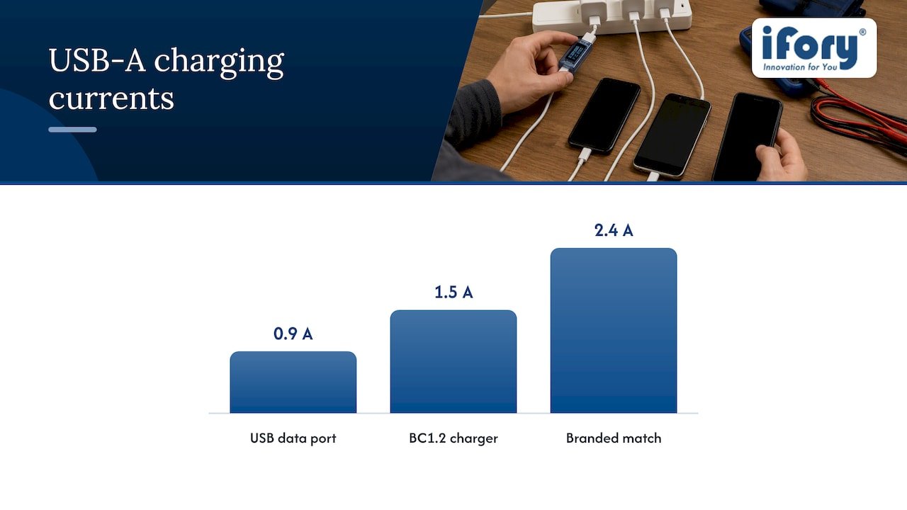
The trade-off is interoperability. A charger built around one vendor’s proprietary handshake might deliver only the BC1.2 baseline, often 1.5A, to a device that doesn’t speak its particular dialect. Field measurements commonly show phones pulling around 1.5A (about 7.5 watts) on a generic BC1.2 charger, with some branded combinations reaching up to 2.4A (approximately 12 watts) when both ends recognize each other, a pattern documented in USB-A hardware references. Mix brands and you often get the lowest common denominator, not the advertised peak.
USB-A to USB-C cables: when higher wattage claims hold up
A USB-A to USB-C cable is still, electrically, a USB-A connection at the source end. The USB-C plug on the far side doesn’t grant the cable PD negotiation capability, because PD negotiation runs through CC pins that originate at a Type-C port, and USB-A has none. Any A-to-C cable or adapter claiming PD speeds is either describing the device at the other end incorrectly or using a nonstandard trick.
What does change with cable construction is how much of the available current actually reaches your device. Follow this sequence when evaluating a cable:
- Check the conductor gauge. Thinner wire, often 28 AWG for signal pairs, carries meaningfully less current before voltage drop becomes a problem; heavier 24 AWG power conductors handle higher sustained current with less loss over the same length.
- Account for length. A short, thick cable loses less voltage than a long, thin one carrying the same current, which matters most near the 2A to 2.4A range where margins are already tight.
- Verify the source port, not just the cable. A premium cable rated for 3A does nothing if the USB-A port behind it only implements baseline BC1.2 at 1.5A.
- Treat “100W USB-A cable” claims with suspicion. At 5V, 100 watts would require 20A, an amperage no USB-A connector or standard cable gauge is rated to carry safely; such claims almost always describe the capability of the USB-C end paired with a different, PD-capable source.
Manufacturers that advertise unusually high currents over USB-A sometimes achieve it by repurposing pins or adjusting internal wiring in ways that fall outside the USB-IF’s form-factor assumptions. That can work with a matched charger and cable, but it risks connector damage or data-line interference if paired with unrelated hardware.
Pro Tip: Trust the current rating printed on the charger itself over any claim printed on the cable: the cable only has to be capable of carrying that current, while the charger’s circuitry is what actually decides how much it sends.
Multi-port chargers and hubs: how shared power budgets work
A multi-port USB-A charger or hub doesn’t necessarily give every port its full rated current simultaneously. The USB-IF’s guidance for powered hubs treats the upstream connection, the single cable feeding the hub from its power source, as a shared budget that downstream ports draw from collectively.
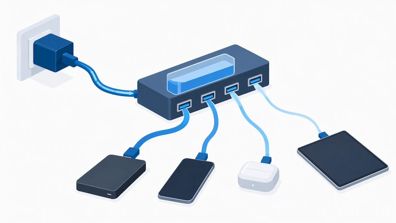
Well-designed hubs implement independent current limiting per downstream port group, so one overloaded port doesn’t drag down the others or trip a single shared fuse for the whole device, a design practice outlined in USB-IF’s hub documentation. But independent limiting doesn’t mean independent total capacity. The USB-IF’s own white paper on powered hubs lays out example power budgets, illustrating scenarios where a hub’s total upstream allocation, in one worked example around 14.25 watts, has to be divided among several downstream ports according to what each one negotiates, as detailed in the Upstream Facing Port Powered Hub White Paper.
What this means practically:
- Plugging in more devices can reduce per-port current once the hub’s total budget is spoken for, even if each individual port is rated higher in isolation.
- A charger’s printed total wattage is a ceiling, not a per-port guarantee. A “60W, 4-port” charger rarely means 60 watts available to each port at once.
- Independent DFP (downstream-facing port) grouping is a marker of better design, since it isolates faults and current spikes to a single port rather than the whole hub.
If a multi-port charger’s label lists a shared total alongside individual port maximums, that’s a signal the manufacturer is being transparent about the budgeting rather than letting you assume every port performs at its peak simultaneously.
Safety, thermal limits, and when to retire a cable or port
Current rating on a label is only half the safety picture. Contact resistance, the tiny but real resistance at the connector interface, generates heat proportional to the square of the current flowing through it. A connector pushed near its rated limit for extended periods, especially one with worn or corroded contacts, can run noticeably warm even when the raw amperage looks unremarkable on paper.
A compliant host or charger should include overcurrent protection that shuts down or throttles the port if the draw exceeds safe bounds, rather than letting current climb unchecked. Noncompliant or poorly made chargers sometimes skip this protection entirely, which is one reason unbranded power adapters have a worse reliability reputation than certified ones.
Watch for these warning signs:
- A cable or connector that’s warm to the touch during normal charging, not just under unusually heavy load.
- Visible discoloration, a burning smell, or a connector that feels loose when a cable is inserted.
- Charging that stutters or restarts repeatedly, which can indicate a port’s protection circuitry is intervening because of an unstable connection.
Pro Tip: Retire any cable showing frayed insulation near the connector immediately: that’s usually where resistance rises fastest and where heat buildup starts.
How to test a USB-A port: tools and a repeatable checklist
Testing a port properly takes only a few minutes and basic equipment. An inline USB power meter, the small dongle-style devices that sit between the charger and the cable, gives you real-time voltage and current readouts without needing to break out test leads. A bench digital multimeter offers more precision if you’re comfortable probing exposed contacts, and a programmable electronic load lets you simulate a device drawing a specific current to see how the port behaves under stress.
Follow this sequence:
- Measure open-circuit VBUS. With nothing plugged in but the meter, the reading should sit close to 5V, generally within the 4.75V to 5.25V band the spec anticipates.
- Apply a known load and measure loaded voltage. Using a programmable load or a device with a known draw, step the current up toward the port’s rated maximum (500mA, 900mA, or the BC1.2 current the charger advertises) and watch for voltage sag.
- Compare the sag to spec tolerances. A modest drop under load is expected; a collapse well below 4.75V at rated current suggests a weak power supply, excessive cable resistance, or a failing connector.
- Document anomalies with the exact load and cable used. Noting which cable, length, and current level produced an anomaly makes it far easier to tell whether the port, the cable, or the charger is the actual problem.
A port that holds steady voltage at its rated current and shuts down cleanly past that point is behaving exactly as the standard intends. One that sags badly or keeps climbing in current without any protection kicking in is worth replacing.
Ifory as a design example: handling higher payloads beyond USB-A
A single legacy USB-A port was never designed for today’s multi-device charging demands, and that gap is exactly what purpose-built power banks are meant to close. We built a power bank around a high capacity and fast charging on its capable ports, paired with multiple simultaneous outputs so several devices can draw power at once without the single-port budgeting constraints described above.
Rather than relying on a legacy USB-A port stretched past its comfortable limits, we route higher-power charging through PD-capable Type-C ports that negotiate voltage and current properly with the connected device, the same CC-pin negotiation that USB-A structurally lacks. An LED display shows real-time status so you can see what’s being drawn without needing a separate inline meter, and the rating and structure address the outdoor conditions where charging gear usually fails first: rain, dust, and drops onto rock or dirt.
Judged trade-offs: what we’d actually recommend
If your device supports USB-C with Power Delivery, use it whenever the use case allows. PD negotiation is standardized, interoperable, and documented, which means fewer surprises about what current you’re actually getting. USB-A’s higher-current modes work, but they depend on both ends agreeing on a proprietary or semi-standard handshake, and that agreement isn’t guaranteed across brands.
Accept higher-current USB-A charging for short-term convenience, a borrowed charger at an airport, a hotel nightstand adapter, when you can’t control which hardware is available. But for anything you’re specifying yourself, whether it’s a product design or your own travel kit, prefer the standard with the clearest negotiation protocol. A short checklist: verify PD certification where it matters, check cable gauge for sustained high-current runs, and never assume a printed wattage applies equally to every port on a shared hub.
— Mats
A practical alternative when USB-A ports fall short
USB-A was finalized for a world of 2.5-watt accessories, not the multi-device, high-wattage charging most of us now juggle on a single trip. When that gap becomes the bottleneck, a dedicated power bank built around PD-capable ports sidesteps the legacy constraints entirely rather than trying to push more current through a connector that was never designed for it.

We designed a power bank for exactly that gap: a high capacity, fast charging on PD-capable ports, multiple simultaneous outputs, a waterproof rating, durable structure, and a real-time LED display, all in a body still compact enough to pack for a weekend trip. For outdoor use specifically, a built-in flashlight means one less item in your bag.
- Choose PD-capable ports first whenever your devices support them, since negotiated power avoids the guesswork of proprietary USB-A handshakes.
- Keep a high-capacity backup on hand for trips where you won’t have access to a wall outlet for a day or more.
- Check port ratings before assuming shared performance, especially on any multi-port device you’re relying on for several gadgets at once.
If a single USB-A port has left you waiting longer than you’d like, the Ifory power bank and compatible solar panel are worth a look as a higher-capacity, multi-port option built for exactly that scenario.
FAQ
Is USB Type-A always 5 volts?
Yes, a USB-A port is specified to deliver 5V under both USB 2.0 and USB 3.x, since the connector has no CC pins to negotiate a higher voltage. Any device claiming a different voltage over a pure USB-A connection is relying on a nonstandard implementation rather than the official specification.
Is USB-A being phased out?
USB-A remains extremely common on chargers, hubs, and legacy devices, even as USB-C becomes the default on new phones and laptops. It’s gradually losing ground rather than disappearing outright, and most multi-port chargers still include at least one USB-A port for backward compatibility.
Can USB-A do Power Delivery?
No, USB-A cannot perform native USB Power Delivery negotiation because PD relies on CC pins that only exist on USB-C connectors. Higher currents seen on USB-A chargers come from BC1.2 signaling or proprietary vendor handshakes, not from PD’s negotiation protocol.
What is the maximum wattage of a USB-A to USB-C cable?
A USB-A to USB-C cable is limited by the USB-A end to 5V, so its practical maximum follows whatever current the USB-A source port and BC1.2 signaling support, commonly up to 2.4A (12 watts) in branded combinations. It cannot carry PD’s higher voltage modes, since those require Type-C negotiation on both ends.
How much power does a standard USB-A port provide?
A compliant USB 2.0 port provides up to 500mA at 5V (2.5 watts), while a USB 3.x port provides up to 900mA at 5V (4.5 watts) under the base specification. Chargers advertising more than this are using BC1.2 or proprietary extensions beyond the core USB-A data specification.